
CAN Bus is the protocol standard designed to enable efficient communication primarily between electronic control units (ECUs). CAN Bus is developed by Robert Bosch GmbH and released in 1986.
Some CAN Bus applications:
Engine Control Units (ECUs): CAN networks connect various ECUs like engine, transmission, and ABS to coordinate their operations.
Infotainment Systems: Used for communication between the head unit, speakers, and other entertainment components.
Body Control Modules (BCMs): Manages functions like lighting, door locks, and seat adjustments.
Advanced Driver-Assistance Systems (ADAS): Facilitates communication between sensors, cameras, and processing units to enhance driving safety.
Why is CAN Bus used in automotive?
- Efficiency:
Reduced Wiring: Unlike point-to-point wiring, CAN uses a bus topology, drastically reducing the amount of wiring needed. Less wiring means reduced weight and cost, which is a big deal in car manufacturing.
Speed: CAN can handle high-speed data transmission (up to 1 Mbps), which is essential for modern vehicle functions like real-time diagnostics and control. - Robust Communication:
Error Handling: CAN includes sophisticated error detection and handling mechanisms, which is crucial in automotive environments where electromagnetic interference can mess with signals.
Message Priority: It supports priority messages, ensuring that critical information (like braking signals) gets through immediately, even if the network is busy.
Physical organization

Noise Immunity: Because CAN Bus uses the twisted-pair cable, the external noise that affects one wire also affects the other wire similarly. The differential receiver detects the difference between CAN_H and CAN_L, effectively canceling out common-mode noise.
Voltage Difference: The actual data signal is determined by the voltage difference between CAN_H and CAN_L.
Nodes

A CAN node refers to any device connected to a Controller Area Network (CAN) bus. Nodes can range from simple sensors and actuators to complex devices like Engine Control Units (ECUs). Each node typically consists of three main components:
CPU: The central processing unit that handles the logic and processing tasks.
CAN Controller: Manages the data link layer, handling message framing, error detection, and arbitration.
Transceiver: Converts the data from the CAN controller to the appropriate voltage levels for transmission on the bus (The Medium Access Unit).
Frames
There are two frame format:
Base frame format: with 11 identifier bits
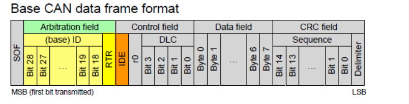
| Field name | Length (bits) | Purpose |
|---|---|---|
| Start-of-frame | 1 | Denotes the start of frame transmission |
| Identifier (green) | 11 | A (unique) identifier which also represents the message priority |
| Stuff bit | 1 | Six consecutive bits of the same polarity (111111 or 000000) are considered an error even if we sent the correct data. Stuff bit helps avoid long sequences of identical bits, which could be misinterpreted as the errors. |
| Remote transmission request (RTR) (blue) | 1 | Must be dominant (0) for data frames and recessive (1) for remote request frames |
| Identifier extension bit (IDE) | 1 | Must be dominant (0) for base frame format with 11-bit identifiers |
| Reserved bit (r0) | 1 | Reserved bit. Must be dominant (0), but accepted as either dominant or recessive. |
| Data length code (DLC) (yellow) | 4 | Number of bytes of data (0–8 bytes) |
| Data field (red) | 0–64 (0-8 bytes) | Data to be transmitted (length in bytes dictated by DLC field) |
| CRC | 15 | Cyclic redundancy check |
| CRC delimiter | 1 | Must be recessive (1) |
| ACK slot | 1 | Transmitter sends recessive (1) and If a receiver successfully receives the frame and finds no errors, it will overwrite the ACK slot with a dominant bit (0) |
| ACK delimiter | 1 | Must be recessive (1) |
| End-of-frame (EOF) | 7 | Must be recessive (1) |
| Inter-frame spacing (IFS) | 3 | Must be recessive (1) |
Extended frame format: with 29 identifier bits
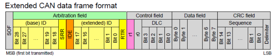
| Field name | Length (bits) | Purpose |
|---|---|---|
| Start-of-frame | 1 | Denotes the start of frame transmission |
| Identifier A (green) | 11 | First part of the (unique) identifier which also represents the message priority |
| Substitute remote request (SRR) | 1 | Must be recessive (1) |
| Identifier extension bit (IDE) | 1 | Must be recessive (1) for extended frame format with 29-bit identifiers |
| Identifier B (green) | 18 | Second part of the (unique) identifier which also represents the message priority |
| Remote transmission request (RTR) (blue) | 1 | Must be dominant (0) for data frames and recessive (1) for remote request frames |
| Reserved bits (r1, r0) | 2 | Reserved bits which must be set dominant (0), but accepted as either dominant or recessive |
| Data length code (DLC) (yellow) | 4 | Number of bytes of data (0–8 bytes) |
| Data field (red) | 0–64 (0-8 bytes) | Data to be transmitted (length dictated by DLC field) |
| CRC | 15 | Cyclic redundancy check |
| CRC delimiter | 1 | Must be recessive (1) |
| ACK slot | 1 | Transmitter sends recessive (1) and If a receiver successfully receives the frame and finds no errors, it will overwrite the ACK slot with a dominant bit (0) |
| ACK delimiter | 1 | Must be recessive (1) |
| End-of-frame (EOF) | 7 | Must be recessive (1) |
| Inter-frame spacing (IFS) | 3 | Must be recessive (1) |
CAN has four frame types:
- Data frame: a frame containing node data for transmission, as described above.
- Remote frame: a frame requesting the transmission of a specific identifier. For example, a central control unit might use a Remote Frame to request the current speed from a speed sensor node. Here is the structure of the Remote Frame.
Identifier: Specifies the data frame being requested.
RTR Bit: Set to recessive (1) in a Remote Frame to distinguish it from a Data Frame.
No Data Field: This contains only the identifier and control info and no actual data.
Control Field: Includes DLC to specify the expected data length.
- Error frame: is a special frame transmitted immediately when a node detects an error. It interrupts the current transmission to notify all nodes of the error, causing them to discard the corrupted frame and prepare for retransmission.
Error Frame is sent
Error Flag: Active (000000) immediately interrupts the current transmission, Passive Error Flag (111111) notifies others of the error without an immediate interruption.
Error Delimiter: Eight recessive bits (1).
Note: the Error Flag sent by a Node is only 6 bits, the secondary Error Flag may be sent from the other nodes. Please refer CAN Bus Errors Explained for more details.
The CAN bus protocol specifies 5 CAN error types:
Bit Error [Transmitter] – Each node monitors the bits it transmits and compares them with the bits on the bus. If a discrepancy is detected, raise the error.
Bit Stuffing Error [Receiver] – detected when receiving more than 5 consecutive bits without a stuffed bit.
Form Error [Receiver] – Detected if receiving a wrong format frame.
ACK Error (Acknowledgement) [Transmitter] – detected by not receiving the ACK from the receiver.
CRC Error (Cyclic Redundancy Check) [Receiver] – detected by recalculating the CRC and compare with the transmitted CRC. - Overload frame: When a node sends an overload frame in a CAN network, it signals that it needs more time to process the previous message or handle an internal event. During this time, the other nodes on the network will temporarily stop transmitting to allow the node that sent the overload frame to recover.
An overload frame consists of two main parts:
Overload Flag: This is a sequence of six dominant bits (0s).
Overload Delimiter: This is a sequence of eight recessive bits (1s).
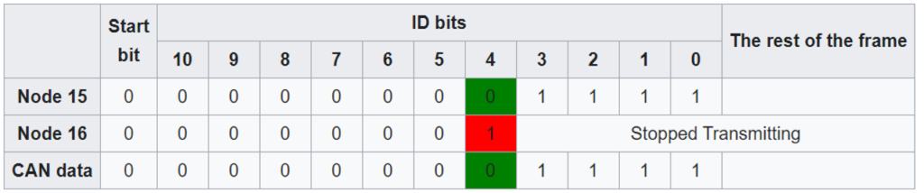
Arbitration
CAN bus uses a priority-based arbitration scheme where messages with lower identifiers have higher priority. In the case, that many nodes send messages at the same time, the lowest identifier is sent first.
Bit timing
All nodes on the CAN network must operate at the same nominal bit rate, but noise, phase shifts, oscillator tolerance, and oscillator drift mean that the actual bit rate might not be the nominal bit rate. To address this issue, CAN bus uses a technique called sampling.
- Synchronization: Nodes on the CAN bus continuously monitor the bus for activity. When a node detects a dominant bit, it starts a timer.
- Sampling: After a predetermined time, the node samples the bit on the bus. If the sample is dominant, the node assumes that it has synchronized with the transmitting node.
- Identifier comparison: The node then proceeds to compare its identifier with the identifier of the transmitting node.
Message filtering
Message filtering allows CAN nodes to selectively receive messages based on their identifiers. This is essential in a network where multiple nodes communicate, as it helps reduce unnecessary processing and ensures that each node only handles the messages it needs. There are three types of Filters:
- Single Identifier Filter: Accepts messages with a specific identifier.
- Range Filter: Accepts messages with identifiers within a specified range.
- Group Filter: Accepts messages with identifiers that match a certain pattern, defined by a combination of mask and match values.
References
CAN bus – Wikipedia
CAN Bus Network Testing | DigiKey
Understanding the CAN Bus: How does it work? (parlezvoustech.com)
CAN_E: Remote Frame | Vector E-Learning
CAN Bus Errors Explained – A Simple Intro [2023] – CSS Electronics